With this article we start a series of posts that will take you from a complete beginner in LTSPice to a master level, that’s why this series is called LTSpice - black belt. This means that we will cover everything from the most basic to the most advanced topics, step by step, so that you have a full understanding of the subject.
What is LTSpice?
LTSpice is a professional electronic circuit simulator, developed by Analog Devices. With it we can simulate several electronic circuits and perform various types of analysis:
- transients
- noises
- DC operating point
- direct current (DC)
- alternating current (AC)
- Fourier analysis
- heat dissipation of components
- DC transfer function
What are the advantages and disadvantages of LTSpice over other simulation software?
Advantages
LTSpice is really free and without limitations. There are several competing programs on the market that offer a free or student version, but that limit the amount of components, the amount of pins, the type of analysis the circuit can do or that prevent you from saving the circuit created and every time the program is closed, you lose everything and have to start from scratch again.
It comes with hundreds of device models from Analog Devices and Maxim Integrated.
Allows the addition of 3rd party PSPICE components / models.
Receives frequent (monthly) updates.
Disadvantages
- Its interface is neither the simplest nor the most pretty. Several competing programs allow the use of virtual equipment, which gives us the feeling of being on a bench. In LTSPice we also have a probe that we can use, but it’s not as realistic as the competitors.
- There are almost no models of devices from other manufacturers (This is easy to solve. You can simply go to the manufacturers website and download the PSPICE models of the components you intend to simulate and add them to LTSpice. We will learn this in a future article).
Is LTSpice for you?
My opinion is biased, but for me LTSpice is perfect for you, because all its advantages are much bigger than its disadvantages.
Would you prefer another program, like Proteus or Multisim for example? Be my guest. They are excellent programs, but they will cost you an arm and a leg. And no, I do not recommend that you download pirated versions. Besides being morally wrong (and a crime), you expose yourself to the risk of having your computer contaminated by viruses and having your data stolen.
How to install LTSpice?
To download LTSpice, go to the LTSpice download page and download the appropriate version for your operating system version. After that, just click on the buttons to continue the installation, accepting the default settings.
Getting to know the default LTSpice interface
You can see in figure 1 the default LTSpice interface. Note that several buttons are disabled. They will only be enabled when we are editing a diagram.
 Figure 1 - Default LTSpice interface.
To create a new schematic diagram, there are 3 possibilities: In the toolbar we click on the button that looks like a play button (figure 2), type the key combination ``CTRL+N``` or in the menu we click on File and then immediately click on New Schematic (figure 3).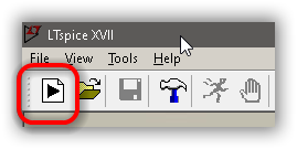 Figure 2 - New Diagram button on the toolbar
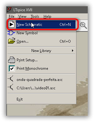 Figure 3 - File -> New Schematic option in the menu for creating a new schematic diagram
Once you have created a new schematic, you can see that several buttons in the toolbar have been enabled.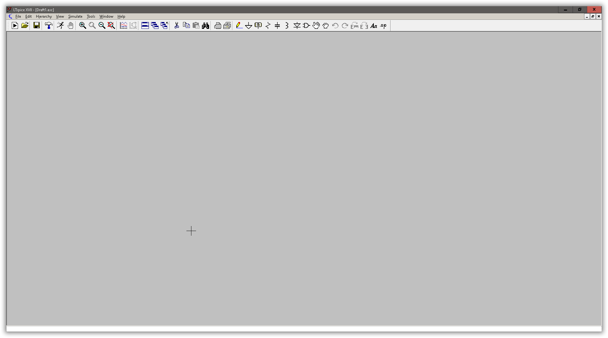 Figure 4 - Toolbar Buttons are Enabled
Buttons and their functions
Before we start editing the schematic diagrams, let’s quickly talk about the buttons and their functions so that you become familiar with them.
Create, Open, and Save
In figure 5 we have 3 buttons on the toolbar: Create new diagram, open an existing diagram, and save the diagram we are currently working on. We can click on them or use the key combinations
- CTRL+N to create
- CTRL+O to open
- CTRL+S to save
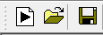 Figure 5 - Buttons to create, open and save a schematic diagram.
Program Settings
The LTSpice settings screen can be accessed by clicking on the button shown in figure 6. Don’t worry about these settings. We will get to them later in other articles. This button has no shortcut key. Figure 6 - Button that gives access to the settings screen.
Simulation buttons
There are 2 buttons related to simulation. The Run button, which runs the simulation, and the Halt button, which stops the simulation. See figure 7 for the Run and Halt buttons, respectively. These buttons have no hotkey. Figure 7 - Run and stop simulation buttons.
If you run the Run command without having done the simulation setup, the simulation setup window will open for you to adjust the parameters of what you want to simulate (see figure 8).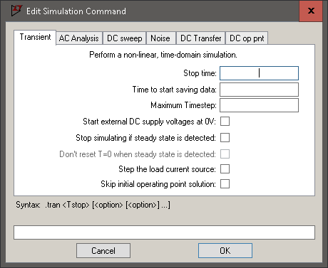 Figure 8 - Simulation configuration screen opened in the Transient tab.
Another way to access the simulation settings is to click on the Simulate menu and then Edit Simulation Cmd (as shown in Figure 9). We will talk more about the simulation settings in future articles.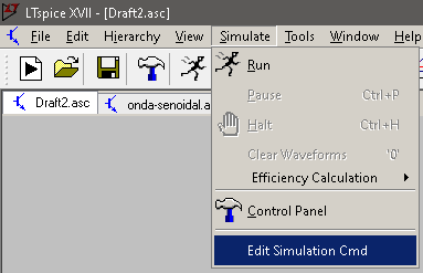 Figure 9 - Accessing the simulation’s configuration screen
Zoom buttons
For the zoom functions we have 4 buttons, as shown in figure 10. The Zoom Area (magnifying glass with the + sign) and Zoom Back (magnifying glass with the - sign) buttons have the following shortcuts, respectively: CTRL+Z and CTRL+B.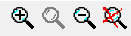 Figure 10 - Zoom buttons.
Buttons interfering with the graphics generated during the simulation
The Pick Visible Traces and Autorange buttons, shown in Figure 11, are available for use when generating graphs. I, particularly, do not use these buttons in my daily life. We will talk about them in a future article. Figure 11 - Pick Visible Traces and Autorange buttons.
Edit and Print Buttons
The Cut, Copy, Paste and Find buttons are the edit buttons and behave as in other Windows programs, in the same way as the print and print setup buttons. See figures 12 and 13.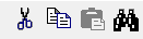 Figure 12 - Cut, copy, paste and find buttons
 Figure 13 - Print and Print Setup Buttons
Schematic Diagram Drawing Buttons
Here we have the buttons that will help us draw the diagrams.
The pencil (shortcut key
F3) draws the electrical connections between components.The ground or reference signal (shortcut key
G) gives us a reference from which the circuit voltages and currents will be measured. It is the ground of the circuit.The little box with the letter A is the label. LTSpice names each of the connections between components as n001, n002, n003, etc. and this is how they will appear in the graphs: V(n001), V(n002), V(n003), etc. For larger circuits, this makes it difficult to identify which point the voltage refers to. So we add labels to the points of interest (e.g. VOUT, VIN, VB1, etc) and these names / labels (labels) will be used in plotting the graph. For example: V(vout), V(vin), V(vb1). And yes, regardless of whether the label is written in uppercase or lowercase, LTspice will show them in lowercase. The hotkey for the label is
F4.The component that looks like a zig-zag is a resistor (hotkey ```R````).
The next component is the capacitor (shortcut key
C).The component that looks like a standing m is the inductor (hotkey ```L````).
The component that represents the diode (shortcut key ```D````) adds signal diodes, zener, etc.
The next component, which is a logic gate, allows me to add all the previous components (resistor, capacitor, inductor, and diode) as well as all the other types of components (bipolar transistors, FETs, operational amplifiers, etc). Its shortcut key is
F2.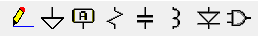 Figure 14 - Image Buttons to draw the schematic diagram
Move and drag buttons
In Figure 15 we see the Move and Drag buttons. Both move the components. The difference between them is that when you move (hotkey F7), any connections that have been made to the component are broken, whereas when you drag (hotkey F8), the connections move with the component.
![Image Move and Drag Buttons] Figure 15 - Move and drag buttons.
Undo and Redo buttons
In Figure 16 we have the undo (Undo) and redo (Redo) buttons, whose shortcut keys are, respectively, F9 and SHIFT+F9. Their behavior is the same as expected in all Windows programs.
![Image Undo and Redo Buttons] Figure 16 - Undo and redo buttons.
Rotate and Mirror Buttons
The rotate button (Rotate - hotkey CTRL+R```) rotates the components 90 degrees clockwise, allowing it to stand or lie on the diagram. The Mirror button (***`Mirror*** - hotkey CTRL+E``), as its name implies, shows the component as if viewed in a mirror.
![Image Rotate and Mirror Buttons] Figure 17 - Rotate and Mirror Buttons
Text and directive buttons
The text button (which contains the letters Aa), whose shortcut key is T, is for us to add any text to the diagram that we see fit.
The Spice directives button (containing the letters .op), whose shortcut key is S, is for adding simulation directives. For example, the type of simulation that will be performed and its parameters, the inclusion of a component model that does not come by default in LSTpice. Unlike the button that adds any text, the LTSpice directive interferes directly in its operation. We will talk more about this button in future articles.
![Image Buttons to add free text and LTSpice directives] Figure 18 - Buttons to add free text and LTSpice directives.
Conclusion
LTSpice is a very powerful software that you can benefit a lot from if you learn how to use it. I recommend that you create diagrams and start playing around with it to familiarize yourself with how it works.
Did you enjoy the tutorial? Then comment there on [Instagram]https://www.instagram.com/plicatibusoftware/) or Twitter. And tell me which tutorials you would like to see.